How to test/rebuild dizzy & alt
First thing you need to do is test all the fuses.
Next you test power at the back wire with a yellow trace. If you have power there good.
Next If you have a LED test light or multi meter you need to check the ignitor wire, connect one end of the test light to the Positive and probe the ignitor wire. if you can reach cank the starter. If your pickups/ecu are good you will have a pulse.
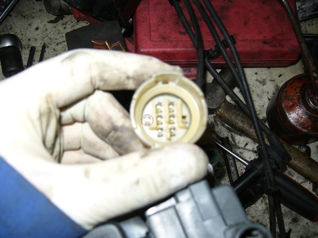
Obd0 dizzies it is the white wire form memory (pin circled). Pretty much on obd0,1 & 2 ite the odd pin out. There will be six pins (they are the pickups) and a single wire.
Remove the dizzy from the car and mount it in the vice. I like to remove the cap and leads as one as I'm lazy haha.
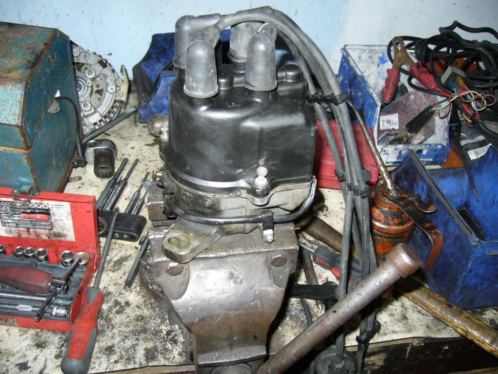
Pull the cap off, 3x 8mm bolts. Now we do a visual inspection. In this case its very obvious whats wrong.
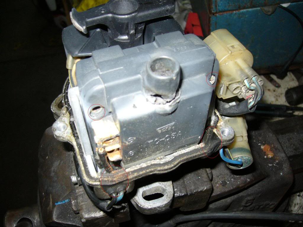
1x sad coil.

Remove the coil by unscrewing the four phillips screws. It helps to have a good screwdriver when doing this as they can be very tight. the bottom screws are covered by the rubber seal. Pull it out to gain access. Screws are circled
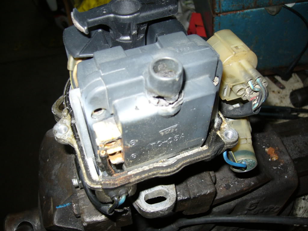
Most obd0 dizzies have coil part number TC-05a and obd1 & 2 TC-08a
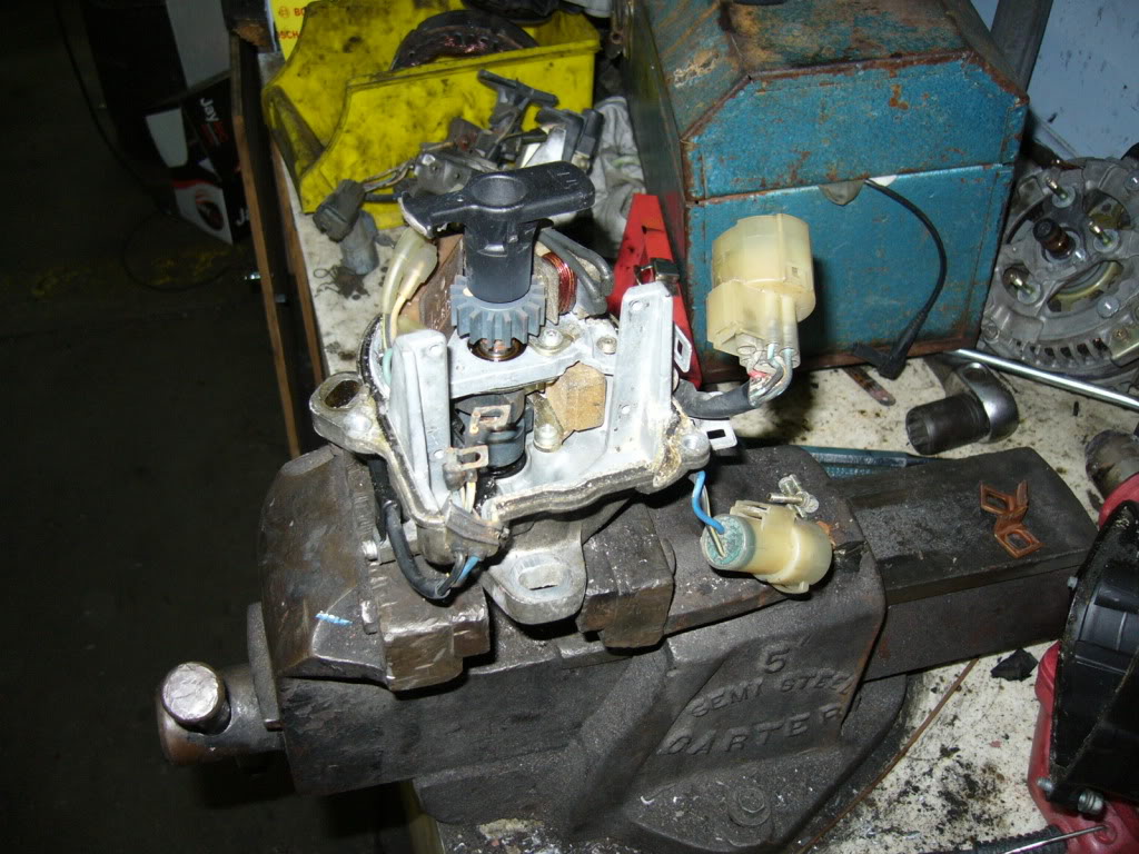
Ideally you will replace faulty parts with new units but if you cant/are a tight ass like me/need to get going.
What I did was raid the dead dizzy shelf at work and grab a coil. If you are using S/H parts its a good idea to test them
I ran the coil up on the coil tester and it went good. Yay.
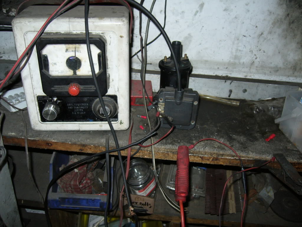
Screw the replacement coil in and put a good cap on and enjoy
I didn't get any pics of how to test the ignitor but I'll do my best to explain.
1. Take the coil out or disconnect the wires from it.
2. Connect the black/yellow wire to power and earth out the body of the dizzy.
3. Connect a test light/multimeter across the two coil wires.
4. Use a jumper wire and tap the ignitor input (circled) wire to earth. If the ignitor is good your test light will light up every time you touch the wire to earth. If you have a multimeter it should read roughtly 12 volts. It is best to use a test light as it puts the igntior under load.

If the light doesn't flash or the meter doesn't display anything your ignitor is bad.
If you don't have access to a coil tester Test the ignitor first and if thats ok chances are the coil is bad.
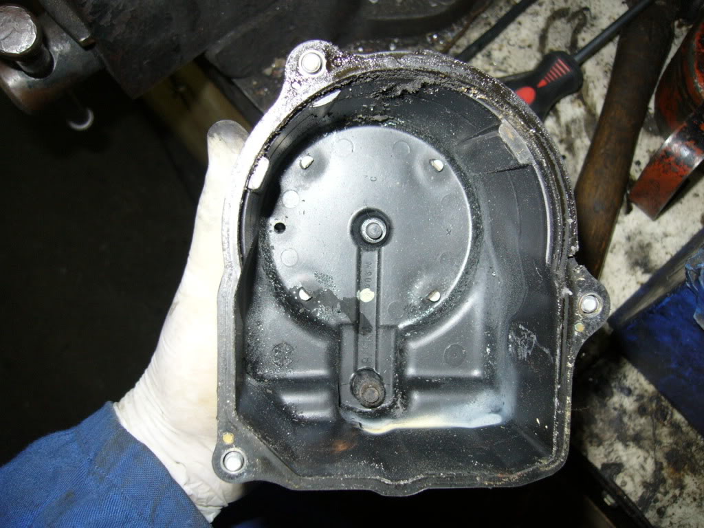
If the cap looks anything like this you NEED to replace it. Make sure the little spacer that contacts the coil is in the cap. otherise your coil will die a miserable death.
Next you test power at the back wire with a yellow trace. If you have power there good.
Next If you have a LED test light or multi meter you need to check the ignitor wire, connect one end of the test light to the Positive and probe the ignitor wire. if you can reach cank the starter. If your pickups/ecu are good you will have a pulse.
Obd0 dizzies it is the white wire form memory (pin circled). Pretty much on obd0,1 & 2 ite the odd pin out. There will be six pins (they are the pickups) and a single wire.

Remove the dizzy from the car and mount it in the vice. I like to remove the cap and leads as one as I'm lazy haha.

Pull the cap off, 3x 8mm bolts. Now we do a visual inspection. In this case its very obvious whats wrong.

1x sad coil.

Remove the coil by unscrewing the four phillips screws. It helps to have a good screwdriver when doing this as they can be very tight. the bottom screws are covered by the rubber seal. Pull it out to gain access. Screws are circled

Most obd0 dizzies have coil part number TC-05a and obd1 & 2 TC-08a

Ideally you will replace faulty parts with new units but if you cant/are a tight ass like me/need to get going.
What I did was raid the dead dizzy shelf at work and grab a coil. If you are using S/H parts its a good idea to test them
I ran the coil up on the coil tester and it went good. Yay.

Screw the replacement coil in and put a good cap on and enjoy
I didn't get any pics of how to test the ignitor but I'll do my best to explain.
1. Take the coil out or disconnect the wires from it.
2. Connect the black/yellow wire to power and earth out the body of the dizzy.
3. Connect a test light/multimeter across the two coil wires.
4. Use a jumper wire and tap the ignitor input (circled) wire to earth. If the ignitor is good your test light will light up every time you touch the wire to earth. If you have a multimeter it should read roughtly 12 volts. It is best to use a test light as it puts the igntior under load.

If the light doesn't flash or the meter doesn't display anything your ignitor is bad.
If you don't have access to a coil tester Test the ignitor first and if thats ok chances are the coil is bad.
If the cap looks anything like this you NEED to replace it. Make sure the little spacer that contacts the coil is in the cap. otherise your coil will die a miserable death.

Comments
Same as the dizzy. Test all the fuses. If ok test the wiring to the alt.
Remove the green plug form the back of the alt and connect the wire of your test light to earth.
Probe one wire at a time. You should have one or two bright feeds and when you probe the warning light wire the test light should glow duller.Sometimes they wont glow at all but the dash light will light up. If all this is good its time to remove your alternator.
Mount the alternator in a vice and remove the shield and battery terminal insulator usually 8 & 10mm bolts.
The first thing I check on denso alternators is the brushes, It is the most common thing to fail.
Unscrew the 2 phillips screws holding the brush holder in. (Circled)
Now take a look at the brushes. If the contact areas on both brushes are shiny they were contacting the slip ring ok. if one is shiny and one is dull you need to replace them. If they are both shiny but very short replace them.
Next you test the rotor. There are two ways of doing this. First way is to get your multimeter and put one terminal on each of the copper contacts where the brushes touch and measure the resistance it should be around 2.6-3 ohms. That works out to be about 4 amps. If the resistance is any less than 2.5 ohms or over 10ish your rotor is buggered and is cheaper to replace the alternator.
(Picture found on google images)
If the brushes and rotor check out good now its time to remove the rectifier (diodes) remove all the screws holding it in and it should look like this. It is a good idea to clean the terminals of the diodes to make it easier to test.Can sort of see the clean spots in the pic.
Now get your test light and connect one end to positive of the battery. Connect the negative to the main terminal (blue wire in pic) probe each terminal and the light should stay off/on (can't remember which) If it changes with one terminal your rectifier is shot. Reverse polarity of your wires and re test each terminal. Now instead of connecting the battery stud you connect the wire to the body of the rectifier (where it touches the cover/cap/where the nuts go) and test each terminal. Reverse the polarity of your wires and test the terminals. If the light glows each and every time you probe the terminals but not after you reverse the polarity the rectifier is good. If your light glows both times or doesn't glow both times on one particular terminal your rectifier is bad.
If everything checks out and your alternator isn't charging changes are your regulator is faulty.
In my case only the brushes were worn and it was a easy fix. I'd say 70-80% of the time the brushes are all that needs replacing.
Any questions just ask.
I'll update this with how to replace bearings when i do the ones in my wagon.