Emmett - 91 RT4WD Wagon
My 3 year quest for an untouched RT wagon finally came to fruition last year. After tons of dreaming, planning and parts searching, I've finally started digging into this baby. The story for how I acquired this gem is long and complicated. Suffice to say, as is with most wagon stories, it took years of searching, a lot of hassle and cost way more than most would expect. But after it all, I'm overjoyed to have it in my possession! I've been working on cars and builds for decades, but have always been a forum lurker and never really a poster. I finally feel like I have a project car worth writing about and documenting, so here goes my first build thread in ~20 years. I guess I better get on with it before forums are completely replaced by social media.
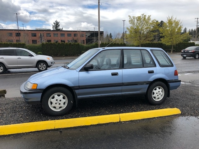
When I got it, it was a bone stock and completely unmodified 1991 blue RT4WD wagon with manual trans and 215K miles. One of the first things I did was get some new tires. These are the smallest all-terrain tires I could find. They just fit without rubbing. LT195/75R14 I think they look great!
So now on with the projects. Here's a list of what I currently have parts for.
- Power Windows
- Power Locks
- Power Mirrors
- Keyless Entry (with hatch release solenoid)
- Cruise Control
- Bluetooth Amp stealthily installed with OE tape deck
- 3 Stage Sound Dampening from SecondSkin Audio
- LED Bulbs for entire car
- New U-Joints
- Inno Roof Rack
- Custom made 6.5" Under-Seat Speakers
- Rockford Fosgate 6.5" 3-way Speakers for the front (will need to make adapters to mount)
- Fill diff mount bushings with 3M window weld to eliminate the clunk
And here's the list of things I have some or most parts for, or that are still in the planning stages. Obviously there's LOTS to figure out for this next section. I haven't even really started on the engine plans yet, but I do have the blue top H23 and clutch.
- H23A DOHC Vtech engine, new clutch and flywheel (installed to look like it came that way from the factory)
- Custom fabricated H2D adapter (I have a friend with a milling machine and lathe)
- Chipped P28 ECU
- Custom fabricated engine mounts
- Custom fabricated AC, power steering, and alternator brackets to align with H23 harmonic balancer
- Custom 2.5" exhaust made to look as stock as possible
- A trip to a good body shop to go over the car and fix all of the little dings and scratches and body color match paint all the black plastic (bumpers, door trim, handles, side skirts, etc.)
- Rebuild 4WD transmission (I have 2 spares and LOTS of extra parts to combine into the best one I can. I'm also trying to build a list of part numbers and sources for as many new parts as are still available)
- Figure out how to retrofit 86-87 RT4WD wagon push-button transfer case actuator and install 4WD button ( I have an 87 trans with linkages and the button but it's missing the actual actuator)
- New Fluid for Viscous Coupler
- New Diff Fluid
- Rear Disk Conversion (just in the dreaming stage at this point)
- Fix the AC and convert to R134 (haven't started diagnosing the issue yet. compressor clutch engages but there's no freon in the system)
- Go through the suspension and check all ball joints, tie rod ends, etc. Nothing feels loose and the car drives great, I just want to check everything.
- Flush break fluid
- Flush power steering fluid
Here's some of the progress I've made over the past week or so. I decided to start on the radio first because I originally wanted to do a "before and after" with the sound dampening. I ended up changing my mind after the OE tape deck I had turned out to be junk and I am waiting on another to ship to me that won't be here until next Wednesday. I didn't want to sit around twiddling my thumbs just so I could do a before and after, so I decided to continue on with the rest of the project while I wait.
First I had to remove this Sony radio adapter and replace it with the stock radio plug. This ended up being unnecessary later on since I took the entire dash out and have a replacement dash harness with uncut radio wires. But the process was still worth while for testing the first radio and to get the ball rolling on the search for a working unit.
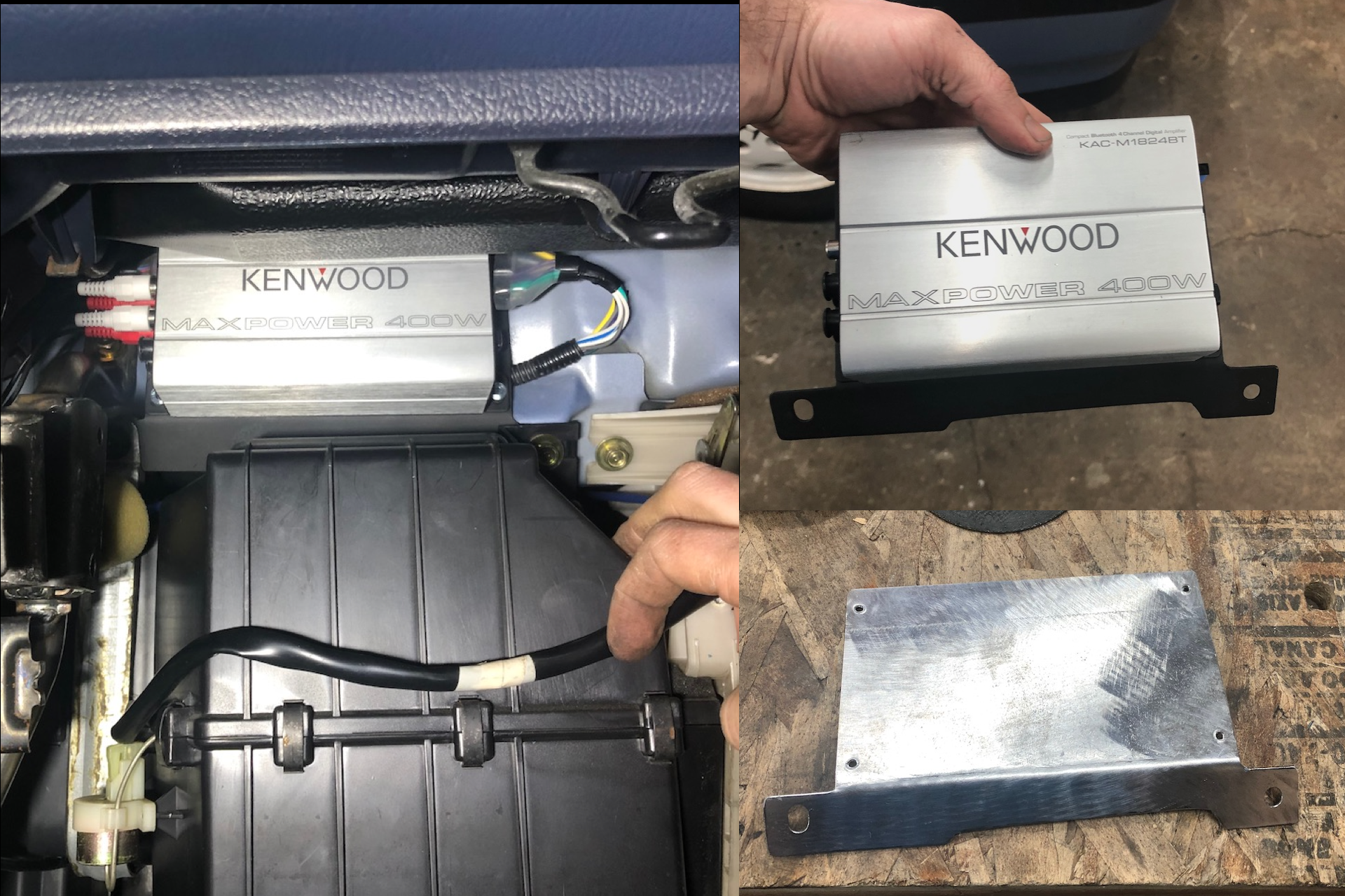
Then I needed to make a bracket and mount the Kenwood Bluetooth amp in a tucked away location. It just barely fits above the AC box.
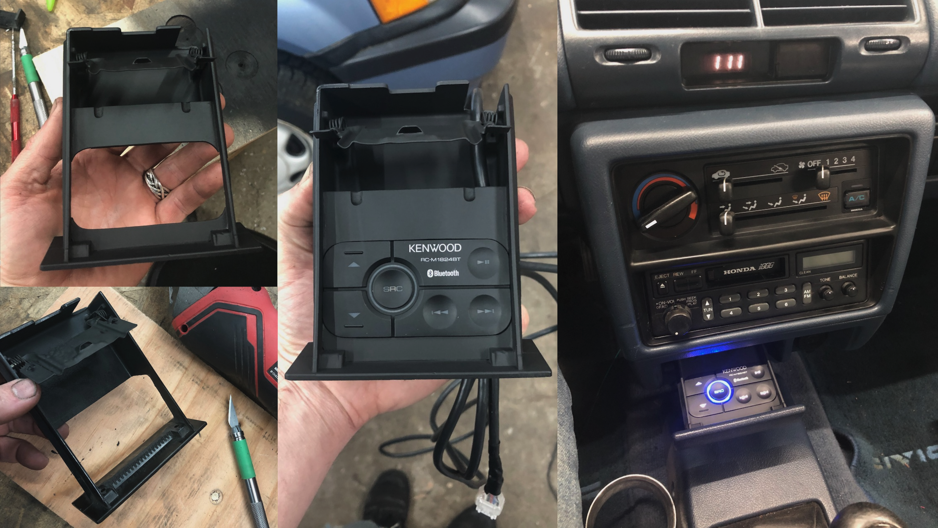
Then on to the control box for the amp. This is the main reason I got this product. With some EXTREMELY delicate dremeling, the control box just fits inside the ash tray. I used some white plastic to make a piece of trim to fill in the gaps and finish off the look. It's super glued in, so here's hoping that it never breaks, but if it does, I have debonder and can dissolve the superglue to remove the back and replace the unit if I need to. I love how it turned out!
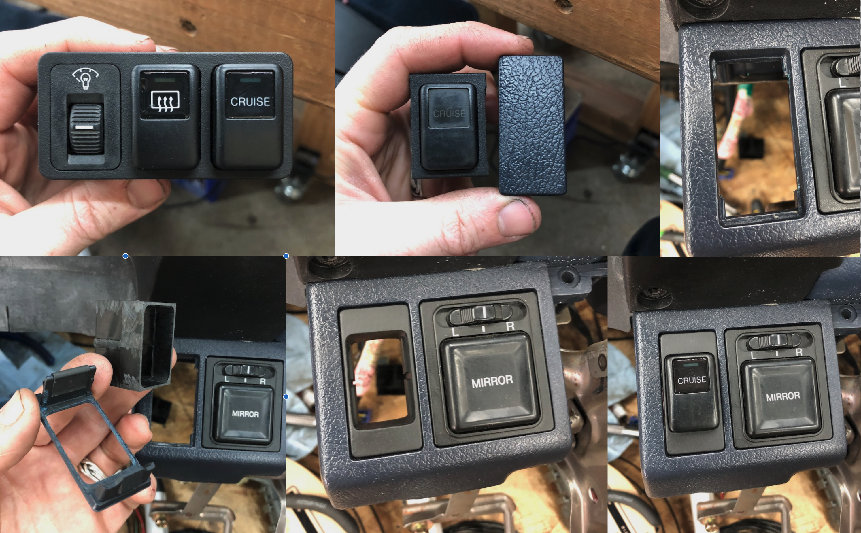
It was at this point that I discovered that OE stereo I got was no good. At least I got everything installed so that I know what the wire lengths will be for integrating into the dash harness. And that leads me to my next couple of steps which was figuring out where the other new buttons were going to go so that I could add their respective connectors to the wire harness in the correct locations. The only new button I was going to put in a non-factory location was the main cruise switch. It is supposed to go on the left side of the gauge cluster in a 3-slot mounting bezel along with the dimmer and rear defrost button, but I don't like that location and it would make the wiring more difficult since those are both on the dash harness rather than the body harness. So, I decided to put it in the slot next to the power mirror switch.
Some more very careful dremeling and super-gluing and a coat of flat black and it looks great!
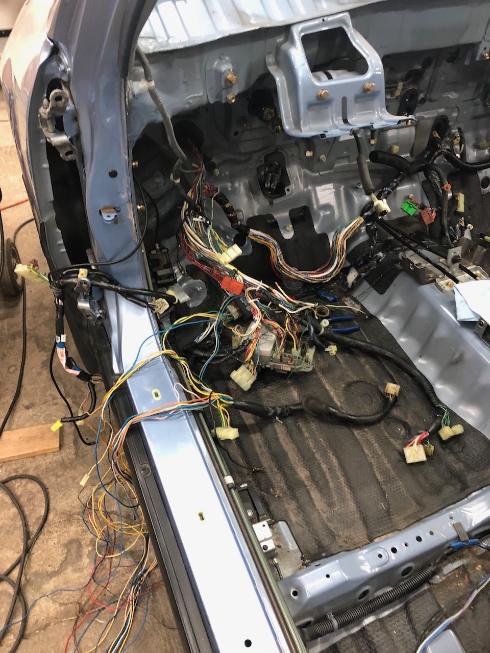
When I collected all the parts for this project, I wasn't very diligent at making a detailed shopping list and the availability of good donor cars wasn't particularly good. I had to drive a few hours to find a blue interior car and I wasn't quite sure at the time about exactly what extent I was going to be jumping into this project, so i didn't pull the complete harness from that first car. BIG MISTAKE. Once I started getting into this, I realized that merging the relevant parts of the sedan harness with my wagon harness was going to be WAY easier than splicing in dozens of wires. But by that point there were no longer any 90-91 5-speed sedans with all the power accessories in my area. The closest was at a pick-n-pull 3.5 hours away and there was no way of knowing if it still had an uncut harness with all the connectors I needed. So, I decided to check out what I could find locally.
The best I could do was an 88 sedan and an 88 SI. The sedan didn't have cruise control but the SI did and the 88's didn't have auto seat belts or the same dash dimmer circuit that the 90-91's have. That meant that the door connectors were different since there wasn't a door latch switch to trigger the auto seat belts and the cruise control gauge light didn't have the dimming circuit on the back of the cluster (I forgot to get that connector from the frst car I pulled the cluster from). All of these different combinations of options started me down a path where I eventually found a solution that I was happy with. I could use the 88 body harness and only have to splice in the cruise control stuff and I could get the cluster plug from the SI (even though it was missing the dimmer circuit wires). This would mean that there would be nothing to trigger my auto seat belts since the 88 door connector is a different size to accommodate a different number of pins.
This is where it dawned on me to do some exploring and see if I could modify the lap belt switch to function the same way at the door switch. This would not only let me eliminate the driver's side door switch and therefore use the 88 body harness, but also it would change my auto seat belts to trigger from me putting on my lap blet rather than from closing/opening the door. Once I started pulling things apart, it was almost like Honda was begging me to do it.
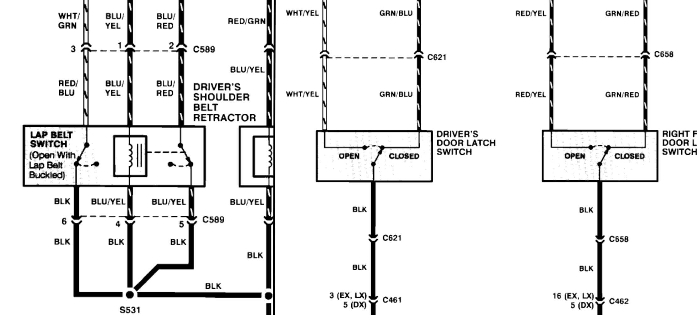
To make the whole thing work I was going to need to add a switch to the passenger lap belt buckle as well as add a second wire to the switch. The door switch is a 3-wire switch and the seat belt is only 2 wire. Here's the diagram.
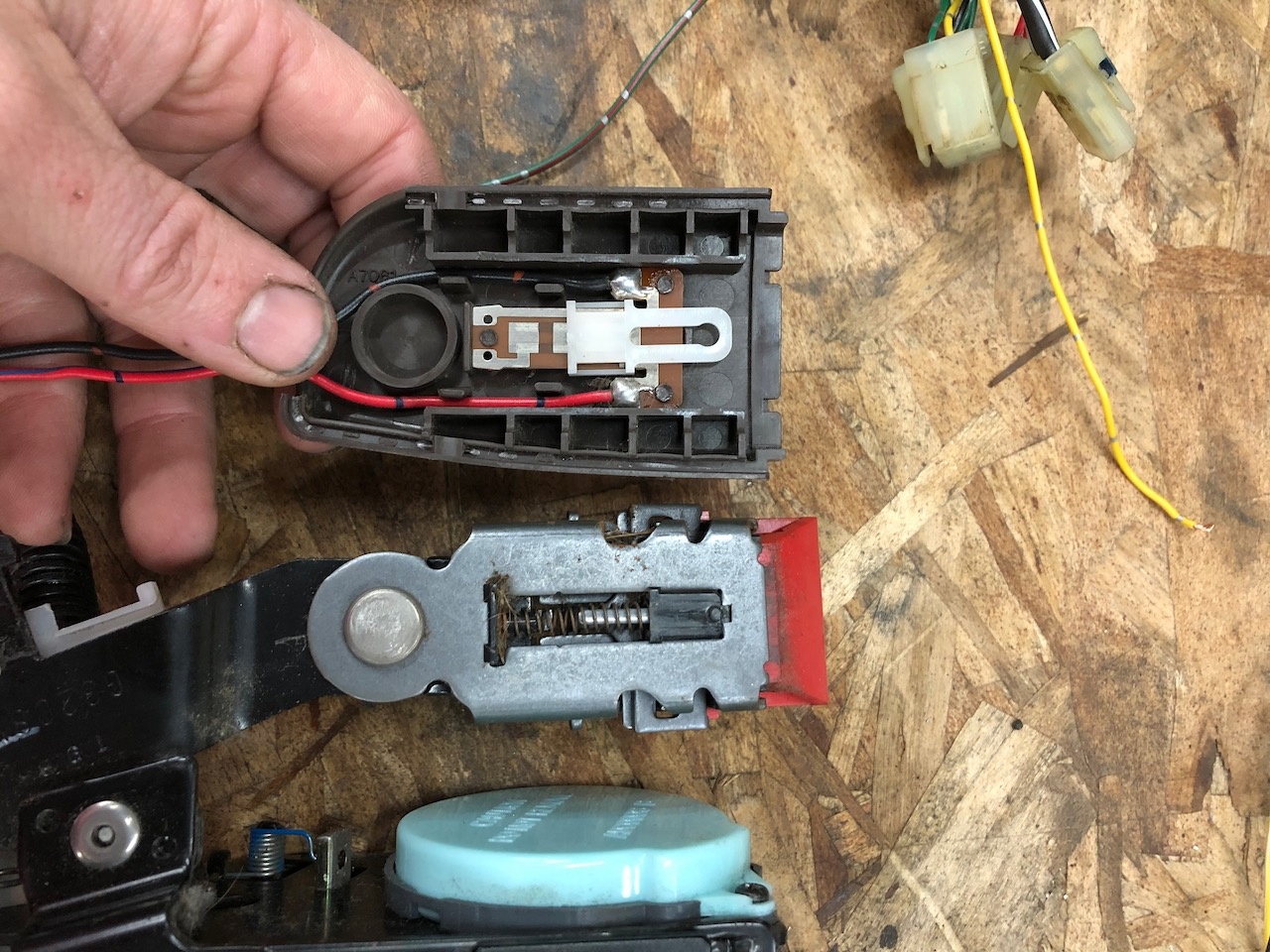
Ass you can see the door switch for the seat belt controller needs to have both an "open" signal and a "close" signal from the door switch, but the lap belt switch is only grounding the signal pin when buckled. Luckily, Honda made the switch with the second position, they just didn't solder a wire in that spot! Here's in the inside of the driver's side lap belt buckle from a donor car.
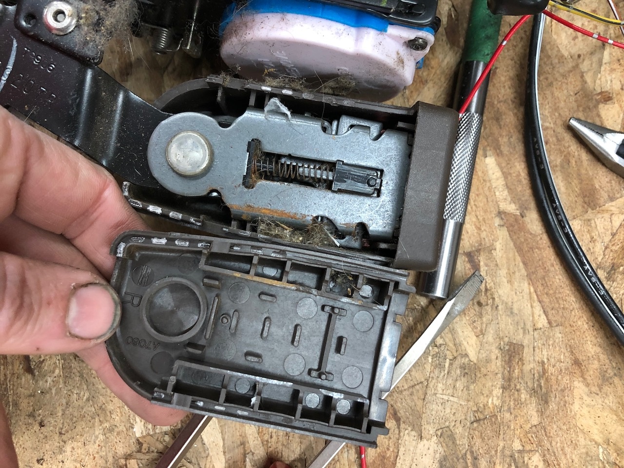
You can see that the bottom pad is connected to the black wire when the belt is bucked. There's even a hole for a wire to be soldered on. So I verified that I could modify the switch, now I needed to see if I could add the switch to the passenger side buckle. The switch is only held in place by 3 melted plastic posts. The passenger side is a direct mirror of the driver's with the same exact slot and posts.
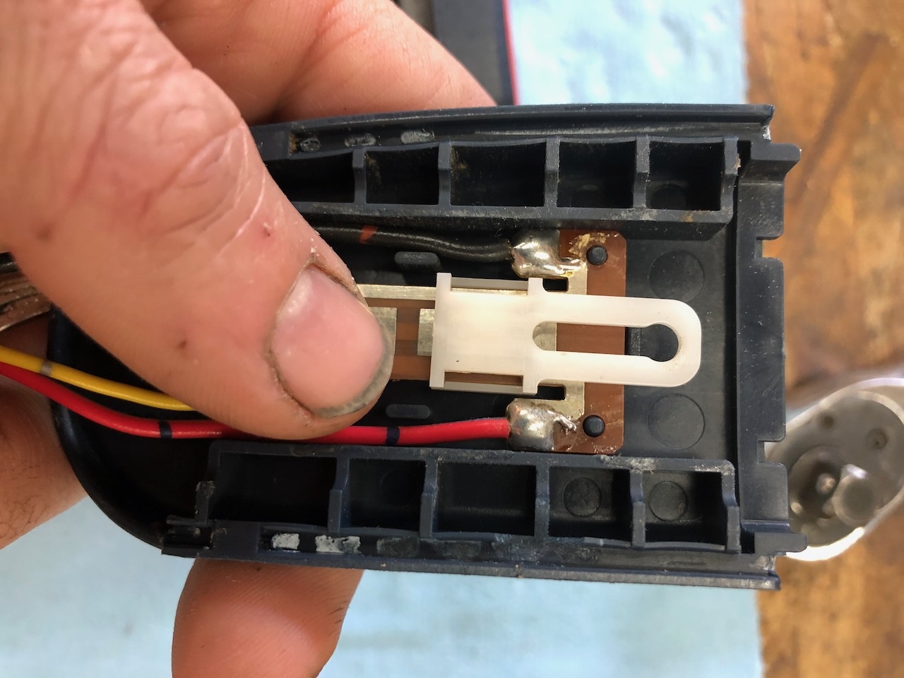
All I needed to do was solder in the extra wire, swap in the switch into my passenger side buckle and melt down the posts.
Then for the connector. The driver's side is a 6 pin and the passenger side is a 4 pin. Of the six pins on the driver's side, 3 of them are ground and are spliced together later on in the harness. Why waste extra money on a bigger connector to have 3 redundant pins? I dunno, but I just spliced two of the grounds together and voila, now I have room for my extra trigger wire.
Now, when I pull the harness apart, I can rewire the door switch trigger wires to this switch instead. There is a possibility that electronically, the seat belt switch (which triggers the seat belt light in the cluster) and the door switch triggers need to be separate. If that's the case, I'm going to wire in a relay to isolate the two different functions that the lap belt switch is now performing.
Now, the last issue is that the passenger side shoulder belt will always be in the forward position unless I have the lap belt buckled because as far as the controler is concerned, it thinks the passenger door is open. This probably wouldn't bother me all that much and I could just unbuckle it unless there is a passenger, but I want to go the extra mile and have a nice experience with it. So I'm going to add another switch under the passenger seat that is pressed when someone sits in it. That switch can then trigger a relay that will swap the functioning on the passenger side door from wither the door switch of the lap belt switch, depending on if there is a passenger or not. Since the door connector for the 88 is the same as the one for the 90-91, it's just missing the pins for the door switch, I can have both switches on the passenger side. I haven't made that switch yet. I'll be sure to post when I do.
The rest of the job so far has just been systematically going through each connector and wire and splicing them in. It's a lot to keep track of, but if you make yourself a lot of notes and labels, it goes pretty smoothly. It's just very very time consuming.
At this point, I've finished everything for the power mirrors, front doors (windows and locks) and the 7 connectors that needed splicing in for the cruise control. Brake switch, clutch switch, steering wheel switches, main cruise switch, controller module, cruise actuator, and cluster connector.
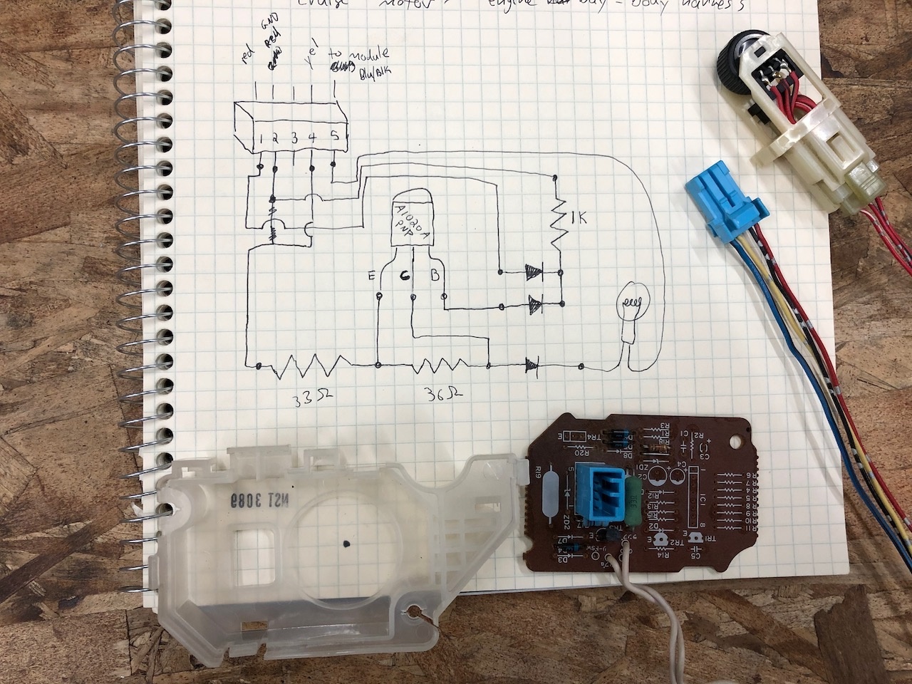
Remember how I forgot to get that cruise dimmer plug for the gauge cluster? Well that came back to bite me when I had to wire it up. Since the 88 has a completely different dimmer circuit, I had to reverse engineer the pins on the connector to figure out what was what. Here is a bad cell phone video of what I did.
So now I'm working on finishing up the dash harness and amp wiring. That's all for now! Thanks for reading!



Comments
@daderaide looks like a clean wagon. Just finished reading everything and wow so much to do! Power windows, mirrors, locks and keyless entry with hatch release sound great to have. H2D don't think I'v every heard of such thing , some guy on FaceBook is in the middle of his H2B in his wagon with the RT4WD, i cant wait to see more updates on this its going to be awesome. Side note wiring gives me a headache or I'm just illiterate with wiring haha.
Love to see someone else digging into wiring and re-making circuits! That was a great read but it was missing something...the back story of how you got the wagon, and who it was from!
The redundant wiring was pretty interesting. I'm curious why Honda would have done that, or where those wires come from otherwise, you've got me curious so I'm opening my Helms manual this afternoon too check. :)
H2D should be interesting. I know that Bisi has one listed on his website, but not sure if he produces them anymore.
Cant wait for more content!
I emailed and called them last year a couple of times about that kit and never got any kind of reply at all. I even tried sending messages on social media pages (facebook and instagram) as well with no luck. Maybe they still have the kits, but with no luck buying one, I gave up and figured I would have to figure it out on my own. Maybe I'll give them another try and see if I can get a hold of anyone this time.
Biisi is notorious about lack of communication unless you can show up at his shop. I ordered a cam from him, it took a looooongg time for delivery and got no notifiication after they accepted the order or shipped. I love his stuff and his passion but unless you are local he doesn't run the greatest business.
Making slow but steady progress. There are just so many minute little tasks to figure out every step of the way. Be prepared for a lot of pictures of wires! I've finished the dash harness and was able to integrate all of the amp wiring into the it. I traced through the fuse box connections and found an empty fuse slot that I could use for main power. Along the way, I've been looking for every possible opportunity to use the factory connectors, wire colors, relays, fuses, etc to keep things as neat as possible. So, I've swapped a lot of connectors around when I needed more pins and I've been reusing pins from other wires when I need a different color. I'm also trying to document all of my wiring harness changes on some schematic print outs so that I'f I have to dig into this again in the future, I'll have some record of how I hooked things up.
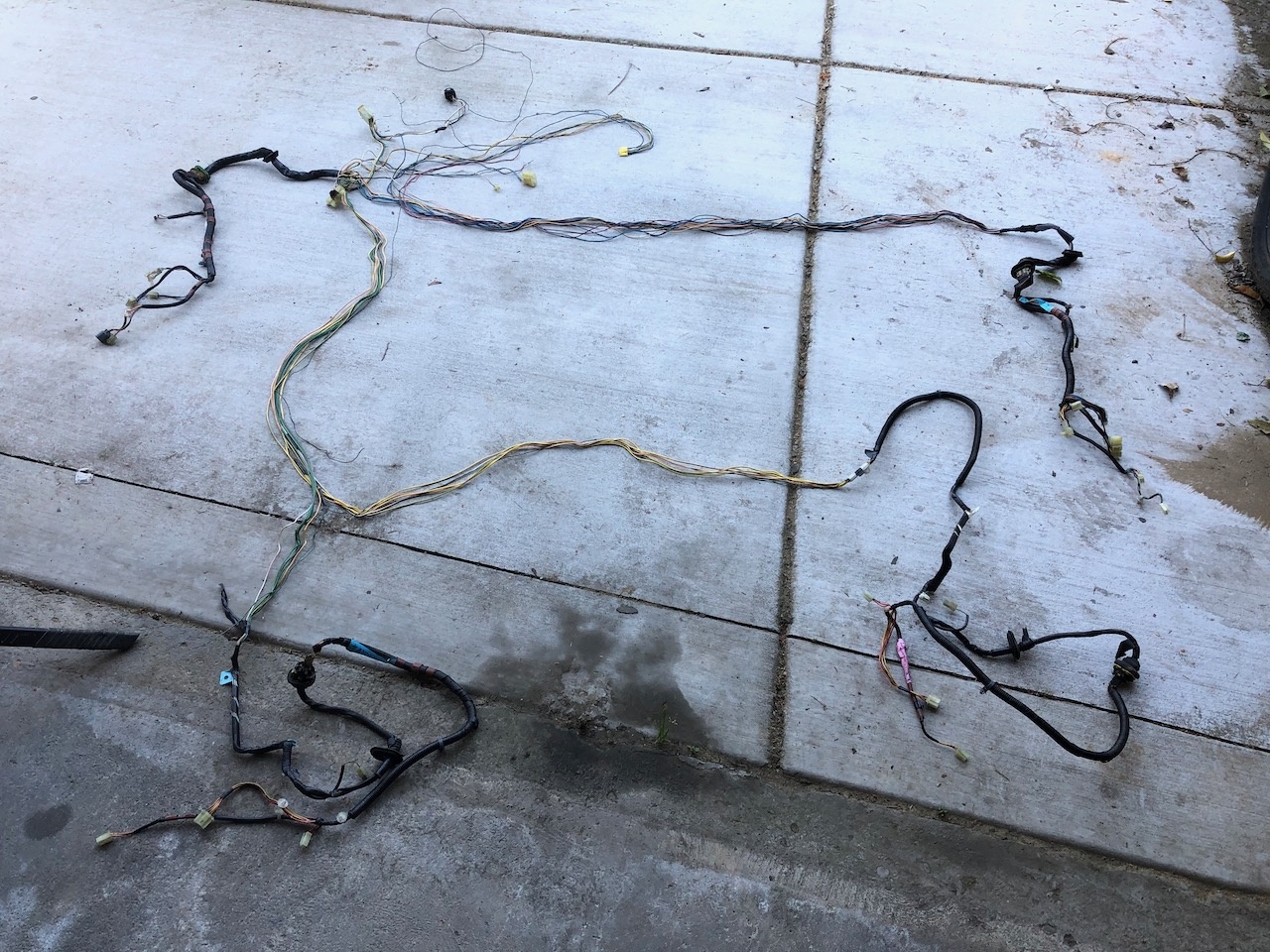
Here's the dash harness before and after.
The 4 RCA connectors on the far right and the connector up and to the left of them are for the amp. I was able to use the various different harnesses that I've collected (I think I pulled 3 dash harnesses all together) to get enough wire so that I could run the output wires directly to the amp from the OE radio without splicing. That's definitely been a goal as well. If I can run a continuous wire from pin to pin without a splice in it, I do. I haven't completely finished wrapping and taping it up yet since I can't fully test it until I get a working OE radio.
Here is the spare fuse box that I took apart so that I could trace the connections for the empty fuse slots.
So far this is my current fuse dash fuse box. The green arrows are the new fuses that are not stock on the wagon. on the left are the 4 fuses for the power windows. 1 fuse for each window motor. In the middle is fuse 9 that I added for the amp. On the right is the fuse for the hatch release solenoid.
Here are the two slots available for relays. The relay with the green arrow is the one for the hatch release and the one next to it on the right is the main relay for the power window circuit. It is turned off unless the key is on, so that you can't stick a coat hanger through the window and push one of the window switches to break into the car. I need to trigger this relay in order to make my remote entry key fob roll the windows down (more about this below).
And finally here is where I mounted the keyless entry module. The coil of wires are the ones I still have left to run. It's super glued to the back of the Integrated Control Unit.
Speaking of the Integrated Control Unit. I popped it's cover open and took out the beeper. I did the same thing with the auto seat belt controller.
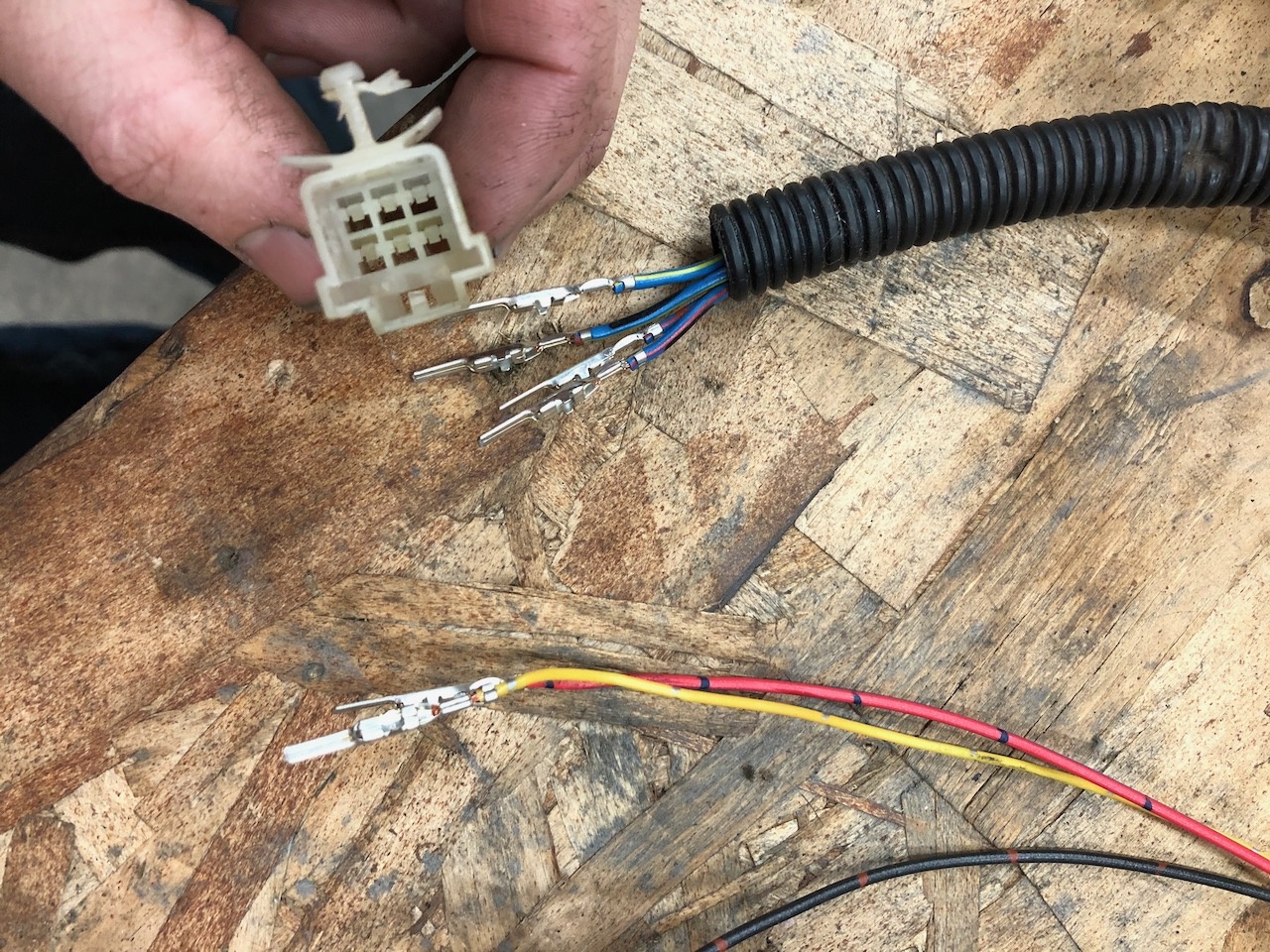
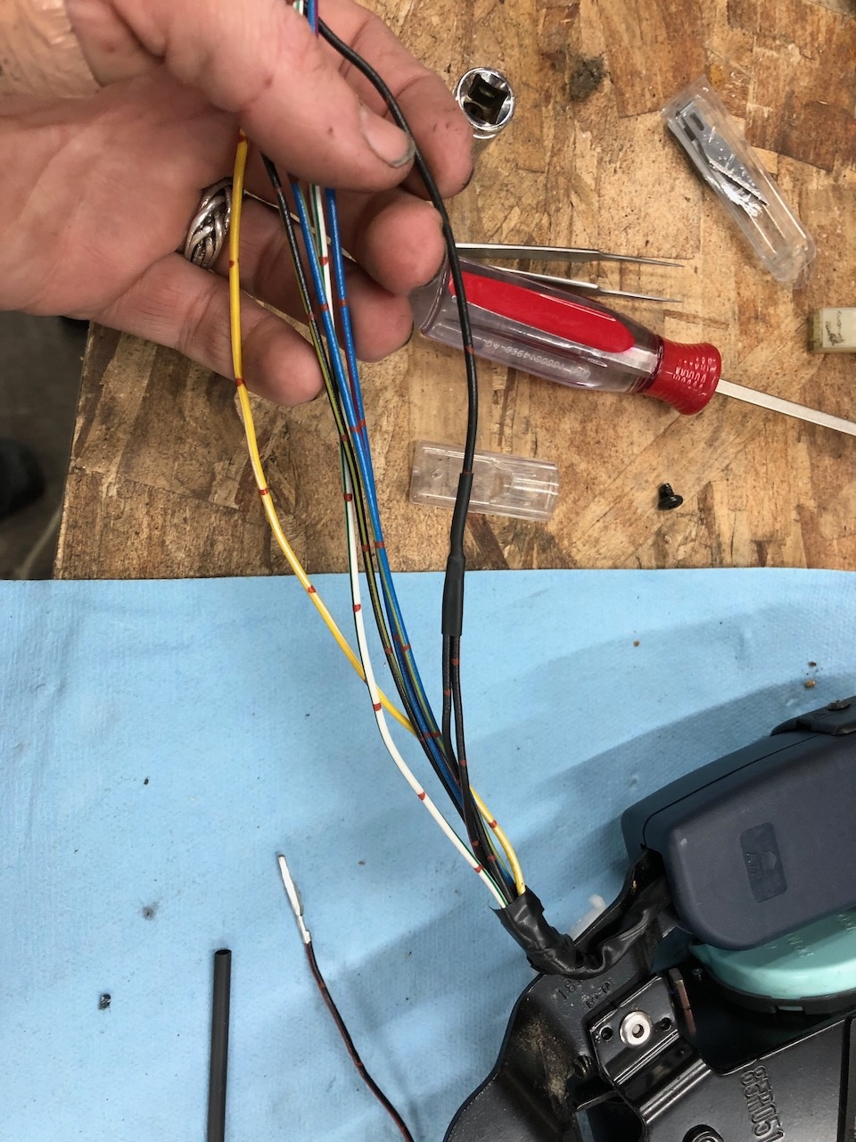
Next I finished up the wiring for the passenger side seat belt switch. This part was kind of complicated because I needed to work out how I was going to get the door switch AND the seat belt switch to both trigger the auto shoulder belt. So, I ran the wires from the door switch to a new connector at the seat. Then I ran the open/close trigger inputs for the control module to that same new connector, as well as the wires from the new lap belt buckle switch (all of this crap is a lot to keep track of and it's one of the reasons that I'm moving kind of slow with it). This new connector is going to be for a "passenger present" trigger switch that I still need to build. Basically, it's just a toggle switch that is pressed when someone sits in the passenger seat. I'm going to mount it to the seat pan touching the foam seat cushion. When someone sits down, it will toggle the trigger input wires for the controller module between the door and lap belt switches. In order to run those 4 wires (2 trigger wires to the module and 2 switch wires from the door) over to the seat, I needed to tap into this connector and add 4 pins. The problem was though, that the connector only had 2 available empty slots, so I had to decide if I was going to add a new connector, or try to swap it for a bigger one. I happened to have a bigger one that with right number of pins that I swapped out of the driver's side, so I used that. Here is the connector before and after.
Here is the original passenger side seat belt plug before and after. The green arrow in the third picture is the new connector that will go to the new seat switch.
Like I said before, whenever I can I am trying to use consistent wire colors and run wires from pin to pin with the least amount of splicing. Here are some of the new wires for this connector. Also a shot of the process I'm using for swapping pins from one wire to another.
Ok, so now I needed to isolate the guage cluster seatbelt warning light wire from the "open" auto seat belt trigger wire. Because of my modification to the lap belt switch, those two wires are now connected to each other so that the buckle switch can perform both functions. After some more digging i discovered that that need to be electrically isolated so I added diodes to each wire. It's called "double diode isolation". I'll be using the same method when I get to wiring the keyless entry into the parking lights.
So what about that power window trigger for the keyless entry that I mentioned before? Well, this keyless entry system as 8 total trigger functions. 8!!! The remote has 4 buttons and you access the additional trigger features by pressing two buttons at once. I tried to think of 8 things that I could have it do, but the amount of time it would take to wire all of that shit in would take forever. Plus, hat would they even be? ejection seat? Flame throwers? i dunno. So, I settled on lock, unlock, hatch release and roll all the windows down. My wife's 2004 Accord has that feature and we really like it on hot days. I am still considering remote start, but since there is no neutral safety switch on the manual trans, I'm not sure I want to put it in. I would also have to bypass the clutch safety switch, which I'm fine with but if my wife drives the car, I don't want her to have to worry about that (or hit a parked car if she forgets and tries to start the car in gear with the clutch out) especially since she is used to driving her accord which is an automatic. So for now, it's just those 4 functions. In order to get the remote to trigger all 4 windows to roll down, I have to splice into each of the window circuits individually and because of the way they are wired into the main window switch, I need SPDT realys or they would all short to ground as soon as I hit the button. I also need to trigger the main power window relay in order to get power to the system. It is a positive trigger relay, but the keyless entry is a negative trigger system :-( So for this one feature, I have to wire in 5 additional relays! 4 relays in the door to keep the window circuits separate and one relay at the keyless entry module to switch it from negative trigger to positive trigger.
Here are the 4 relays mounted in the door. They just barely fit without interfering with the window regulator or the door panel.
I used these square plastic inserts for that OE style mounting.
I also needed a giant 14 pin connector to run all of the connections that needed to be made. I was able to cannibalize an extra window switch and dremel off it's connector. Then I super glued the clip from one of the other spare connectors to it so that it would snap to the door frame in the same sport that the door switch connector used to be. It was such a large connector that this was also the only place behind the door panel where there was enough clearance. Here is the finished driver's door harness. The green arrow is the new connector for the relays.
Here it is all mounted up.
Then I needed to mount the actual switches into the door panel. This was definitely an anxious moment. No going back after this!
Everything fit's great and all the clearances look good.
I'm still working out a plan for what to do with that hole left over from the manual window crank.
I needed a break from all of the wiring and the paint I was waiting on came in, so I decided to go ahead and get all of the bare metal pieces from behind the dash cleaned up and painted. There was very little rust on any of them (the lease amount I have ever seen actually), but there was still small bits of surface rust that needed to be removed before paint. I soaked all of the pieces in this rust dissolver stuff. I prefer Evaporust since it's not acid based and so i don't have to work about splashes or spills but amazon was quoting a few days for it to arrive and my local AutoZone had a rustoleum version in stock (as well as curbside pickup so I don't have to deal with the rona virus shit). It's phosphoric acid based but does a great job and even eats any bits of chipped paint.
I also use the painting step as a motivator to work on swapping the cruise control pedal over so that i could paint the pedal assembly. According to the write ups I have seen for doing the cruise control swap, the two pedal assemblies are supposed to be a direct swap, but on my wagon, the clutch pedal pivot is in a different place. This means that when I test fit the sedan pedal, my clutch cable was way too short. Maybe it's something to do with the RT transmission? Maybe I was supposed to get the clutch cable from the sedan? I'm not sure, but I decided that it was pretty easy to just cut off the throttle pedal sections and weld it on to my wagon pedal assembly. Since I was already taking it all apart to paint it, and there aren't any 5-speed cruise control cars within 300 miles of me at the junk yards, I decided cutting and welding was the way to go. Here is the difference in clutch pedal pivot location.
Here are the two pieces cut from their respective assemblies and ready to be cleaned and welded.
And then paint!
Here are the rest of the pieces after painting so they can fully cure before I put them back in the car.
That's my current status. I'm waiting on some 5A schottky diodes so that i can finish wiring the parking lights into the keyless entry (it flashes them when you press lock) and for wiring into the power window relay. Next up I think I'm going to work on mounting and hooking up the hatch release solenoid, fabricating the seat switch and cutting the hole in the firewall for the cruise control actuator cable.
I love the detailed work your doing on this wagon. I've taken my pedal assembly out a few times but never thought of an acid bath for it. I've always just used a dremel and steel brush. Your way seems a lot easier! Looking forward to more updates!